Recent searches
Search options

Administered by:

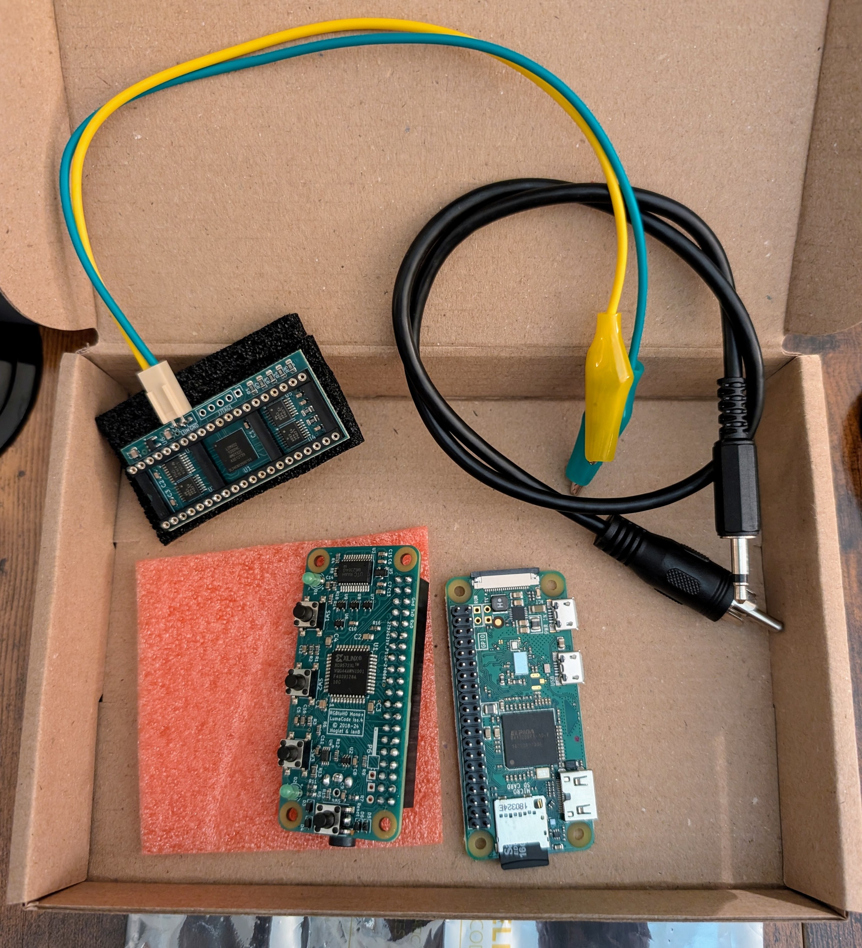
I just received my VIC-II-dizer, a clever hack which produces a crisp HDMI output for the #C64 by snooping the data bus of the video chip.
Other solutions typically digitize the analog luma/chroma outputs of the VIC-II or replace the entire chip with an FPGA replica.

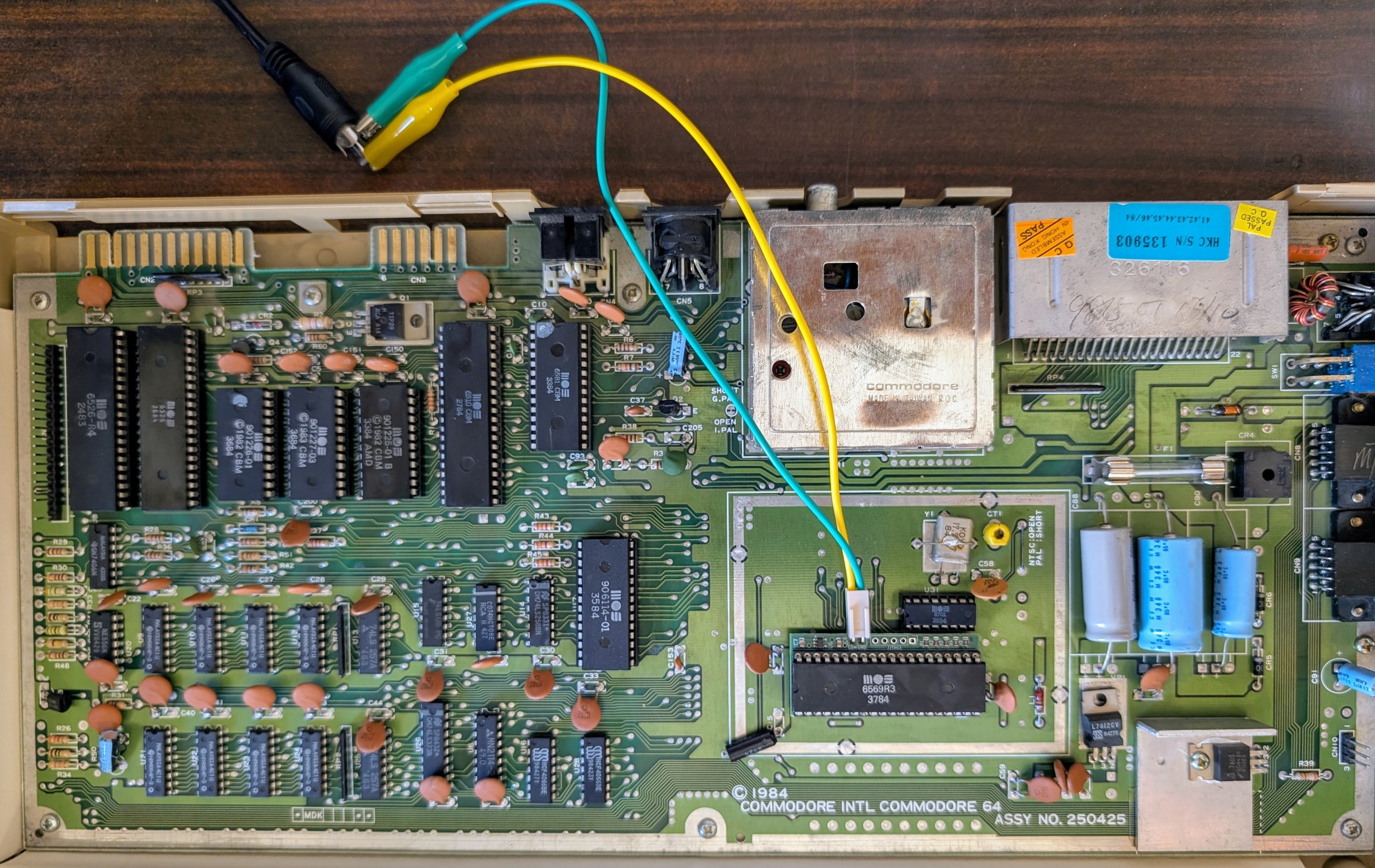
Unfortunately, I can't test the VIC-II-dizer today because the only #C64 I have broke down last week 
I've already checked for power issues and basic bus connectivity, but I can't go any further without an oscilloscope and/or a diag cartridge. And then I will likely need to order a new IC somewhere...
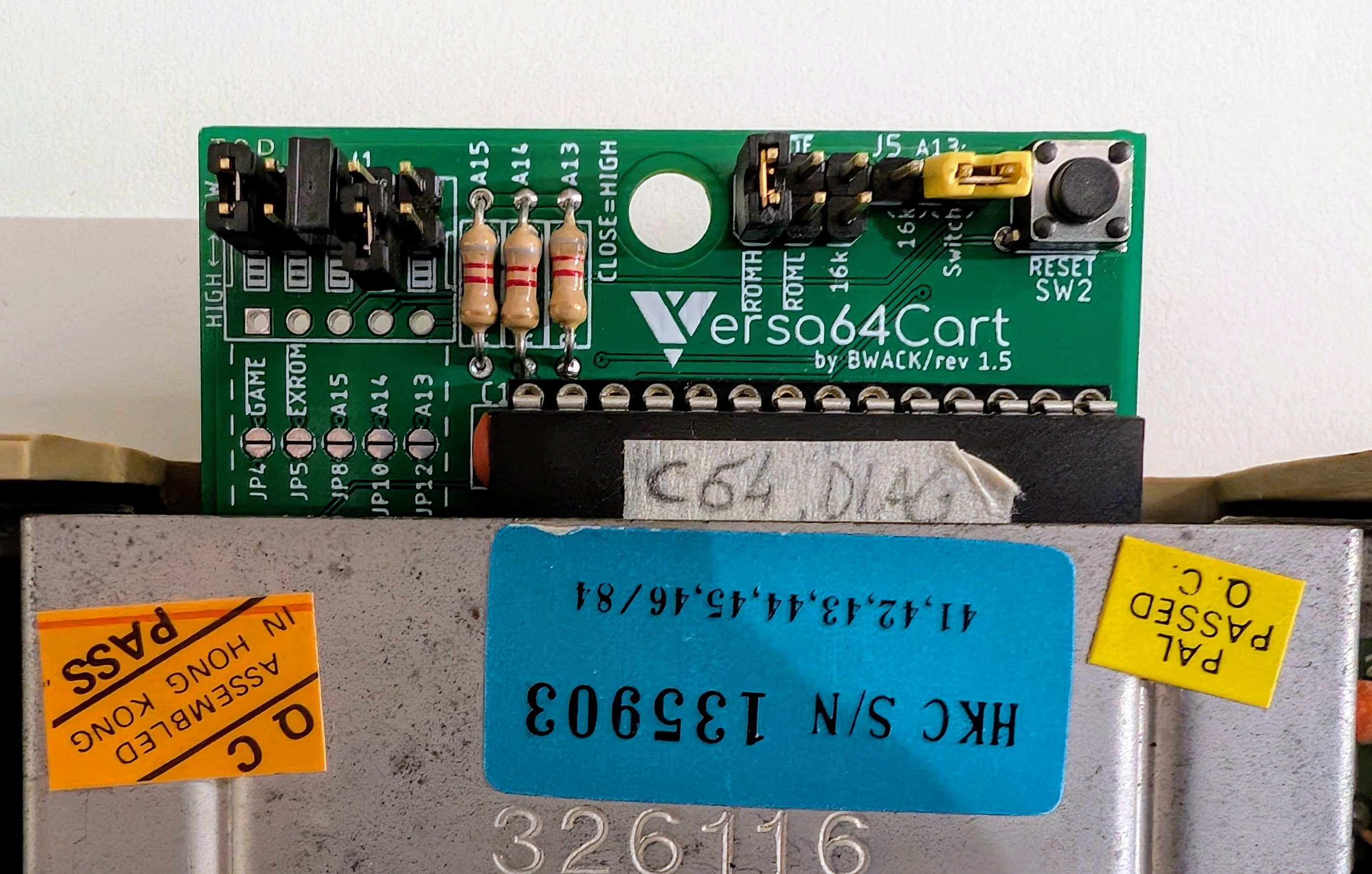
I borrowed a Versa64Card from my friend @giomba.
To help diagnose the fault, he pre-programmed a flash with 4 different diagnostic ROMs which can be switched by holding the top address lines either high or low.
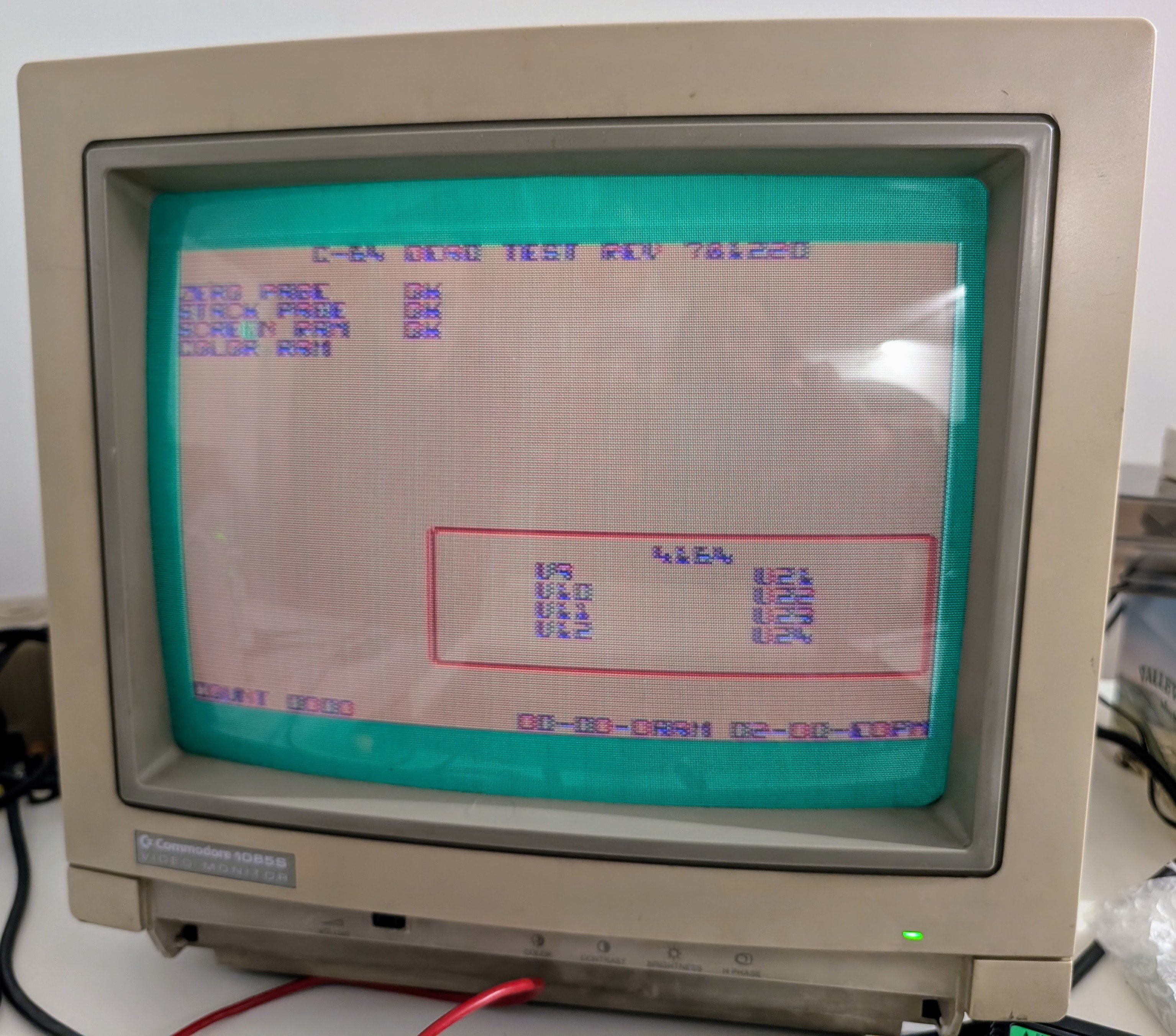
Of these, Dead Test has the best chance of running on broken boards: it sets the #C64 to "Ultimax mode" and doesn't rely on the KERNAL ROM. In fact, Dead Test can run with most chips pulled out except for the PLA, VIC-II and, of course, the CPU.

It works! With all chips pulled out, Dead Test starts! The funky colors are a pre-existing quirk of this VIC-II, something I was hoping to workaround with the VIC-II-dizer I bought.
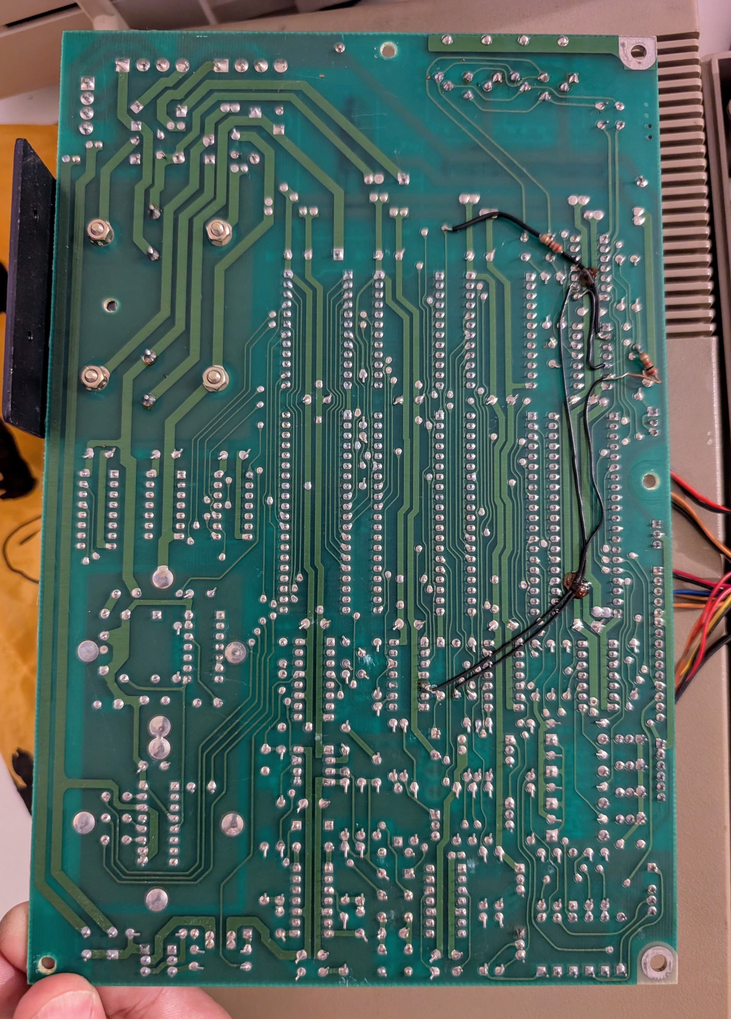
We reseat the chips one by one, until... Aha! Installing the CHAR ROM in U5 causes even Dead Test to... die! 
Looks like two chips are fighting to drive the data bus lines.
Is the chip-select pin shorted to ground, causing the CHAR ROM to respond on every bus cycle? That would surely mess everything up!
Lifting the chip-select pin out of the socket and hooking it to +5V with a resistor fixes things, suggesting the ROM is actually working fine.
The real culprit is whatever holds the CHARROM chip-select signal low at the wrong time 

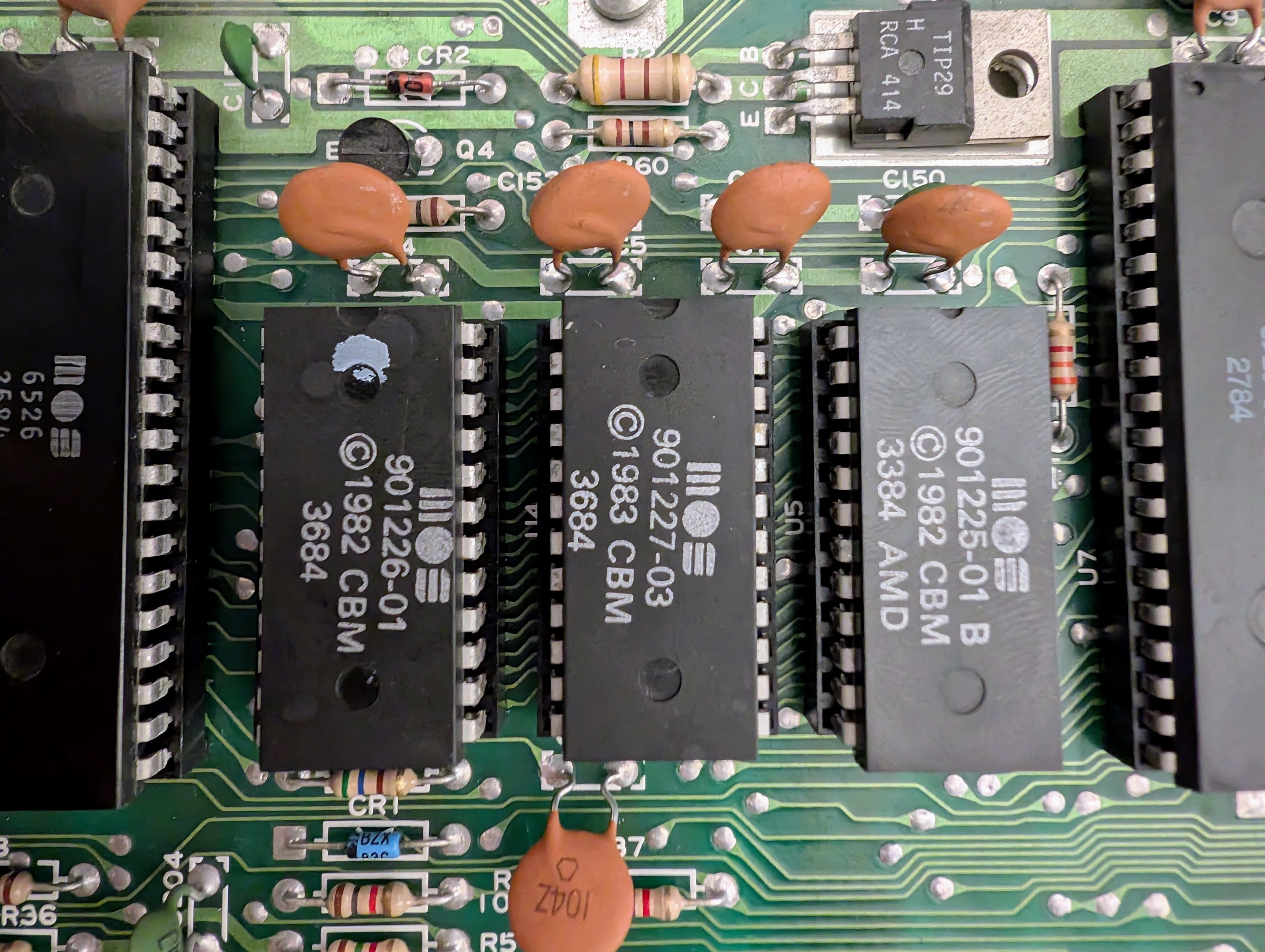
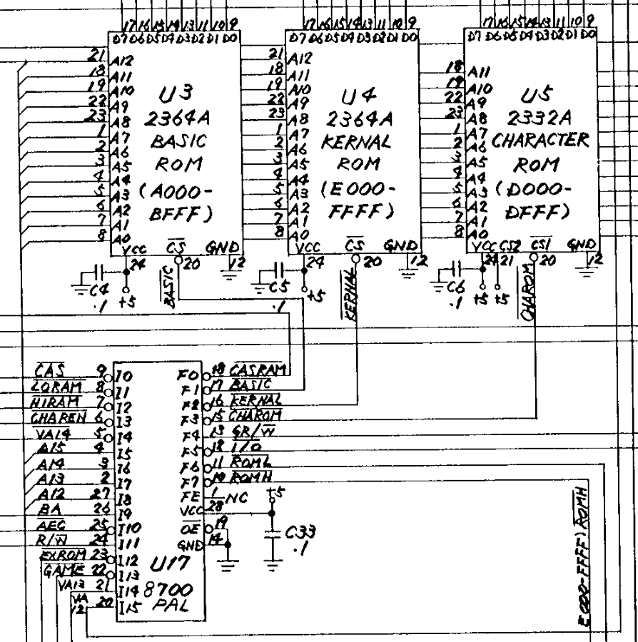
...and this leads to the PLA. Yes, the goddamned 906114-01 which consolidates the #C64 address decoding logic and controls all the chip-select lines on the board.
I'm not at all surprised: these old MOS PLAs are known to die often. Though I wasn't expecting that a single output would change behavior while the rest appears to work fine.
Perhaps a single bit-flip in the programmable gates which control boolean equations? 
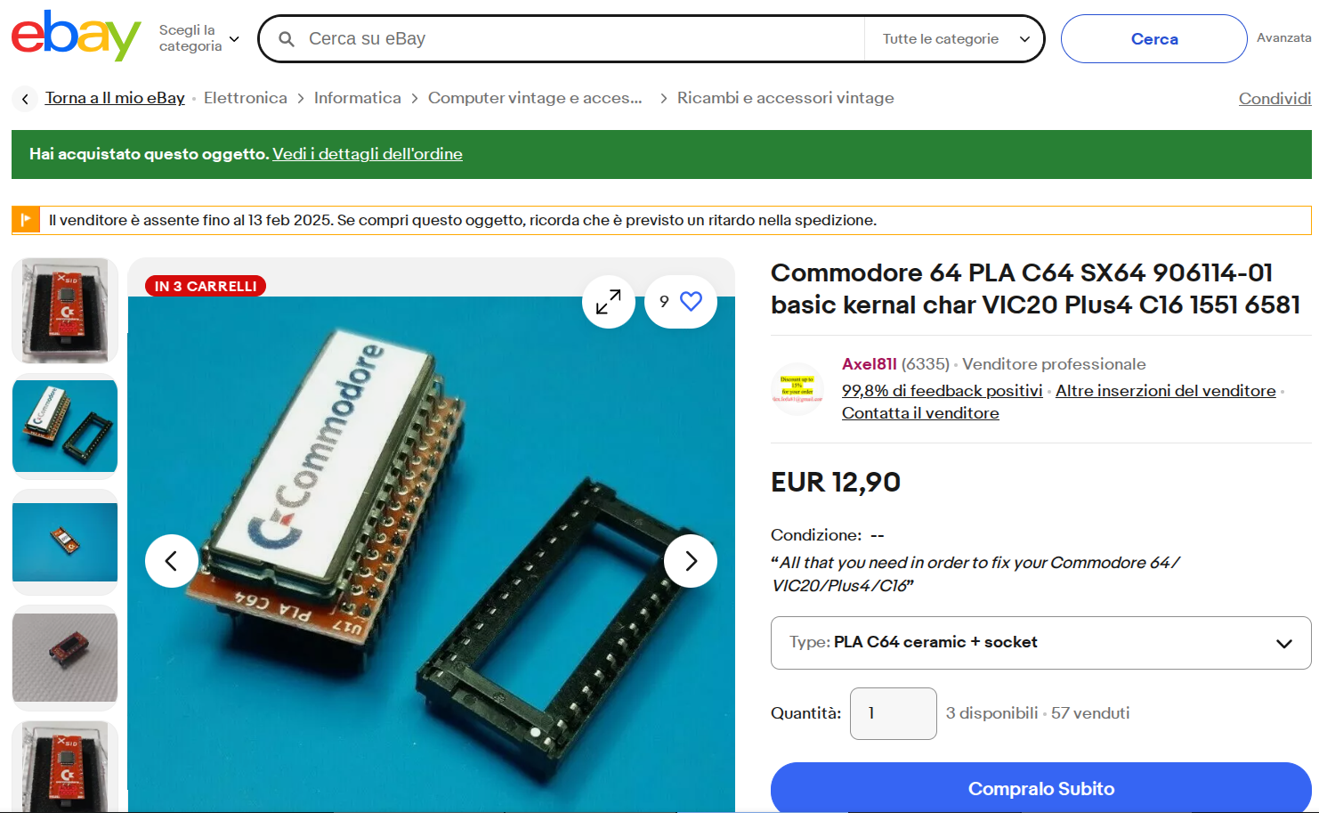
Thankfully, #retrocomputing stores offer a number cheap #C64 PLA replacements nowadays.
I ordered this one, along with a couple of adapter sockets to plug standard 27Cxxx EPROMs into one of the MOS 2364 ROM sockets.
This will make the ROMs easier to replace in the future, and also enable replacing the stock BASIC and KERNAL code with one of the many enhanced ROMs floating around.

@codewiz don‘t give up! C64s can always be repaired!
@codewiz could still be a broken PLA…
@root42 You were right! Check the rest of the thread for an update.

@codewiz Maybe the bonding wire for that line got loose and touches GND now?
@patrick I checked: if I remove the PLA, I can easily pull that CHARROM line high with a 1k resistor.
@codewiz I have a few GAL PLAs left over if you need one. They are of higher compatibility usually, as the EPROM timings are sometimes not good enough, from what I heard.
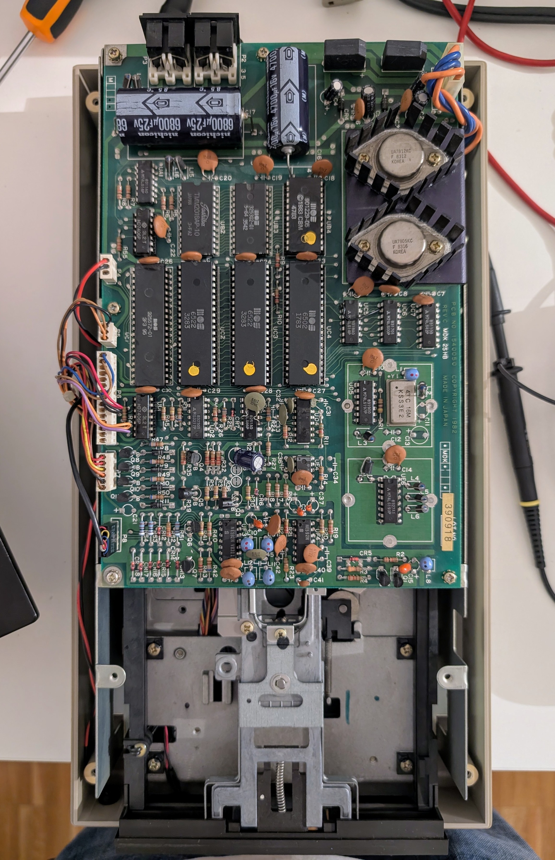
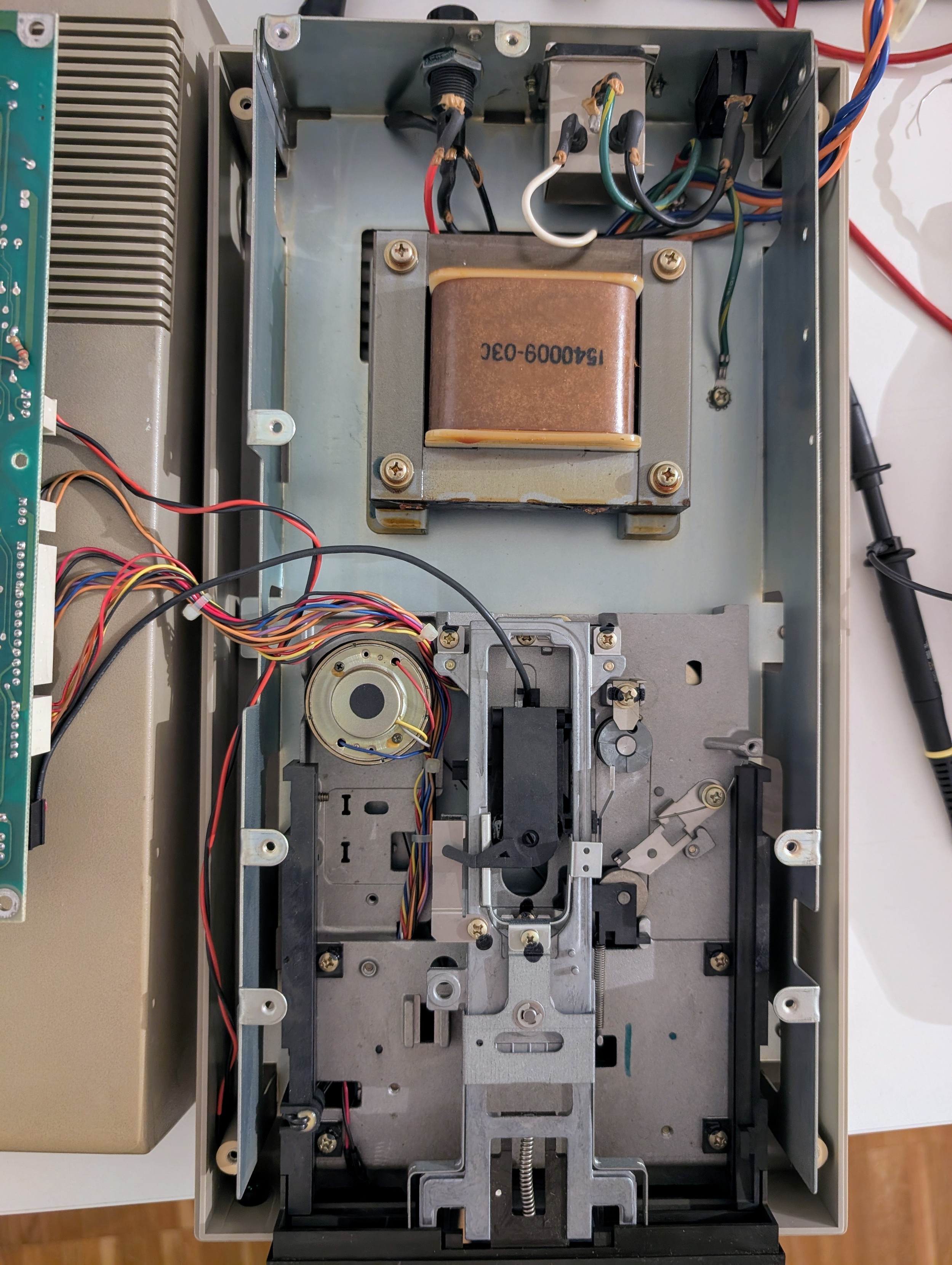
@root42 If I could bother you with my restoration projects, I'd rather ask you to look into this broken 1541.
I replaced UD3 to fix an _RST signal that looked too low and too noisy, and now there's some CPU activity and very short LED blinks, suggesting a reset loop (it's not one of the diagnostic flash codes).
It's harder to see what's going on witth a computer lacking a screen and diagnostic cartridges... I'll try replacing both ROMs when I get the 27C64 adapter socket and the programmer.
@codewiz Did you go through the basics? Good power lines, clock signals?
What does the reset line say? Does it go low again, or just low, then high?
@root42 Power and clock looked good. Some IC output levels are more like 4V and look a bit noisy, but that's probably expected from MOS and TTL logic of this era.
Now RST and INT look good, and I see bus activity and CS being toggled on the ROMs. without an in-circuit emulator or a logic analyzer, I can't tell where the CPU is stuck.
My next move would be replacing the ROMs and maybe try a 6502 from a VIC20 to see if anything changes.
@codewiz so far I only ever saw ROMs fail on this side of a 1541. But who knows... I would also check all the chip select lines for the ROMs and VIAs. Those have to be working correctly to avoid bus conflicts. How does the data on address and data bus look?
@root42 All the signals on the bus look normal, except for D1 (pin 32 of the 6502), which looks like there's bus contention or something:
@codewiz can you do a single trigger?
@codewiz ahahah i buyed many items from axel81....he is like a leggend in Italy 
Anyway i use this pla for my c16 and work fine.
I think you can find a GAL one from axel...

@xexer I opted for the "ceramic" one, hoping it's actually an EPROM-based PLA which can be reprogrammed by the Relatively Universal ROM Programmer which I ordered.

@codewiz huh, some of these do 5V...
I think I rated it 3.3 due to the 25FU406B on the back...

@RueNahcMohr Are you suggesting reimplementing the C64 PLA on one of these?
I've already ordered a PLA replacement which, I think, is made with an EPROM mounted on a board.
I don't fully understand how it works, but I guess the EPROM is programmed to contain a fully expanded truth table for the original logic equations, so you can route the PLA inputs to the addresses, and the data lines will match the PLA outputs.
@codewiz eproms work.